
Education Centre
Kronowall 3D Installation Guide
Kronowall is the perfect upgrade for any wall and with easy installation and maintenance, it is the perfect addition to your home.
• Suitable for bathrooms
• Low maintenance & easy to clean
• Heat resistant and suitable for built-in lighting
• Lightfast surface
Watch this video for simple assembly instructions and for a more thorough step-by-step process please see the guidelines below!
Kronowall 3D Installation Guide
Please read through these assembly instructions before and during assembly.
Please follow these instructions precisely in order to retain your full warranty entitlement.
Kronowall 3D is manufactured in defined and ultra-precise work stages. Semi-finished and finished products are subjected to stringent and continuous quality control checks. However, damage to individual panels e.g. during transport, cannot be ruled out entirely.
Please check before and during assembly on the condition of the individual wall elements and accessories under optimum lighting conditions, looking for defects in the materials or damage. If a defect is identified in the products, do not use the product and notify the relevant sales retailer in writing. Once panels have been used, you are no longer entitled to submit complaints in respect of these.
Please be aware of the weight of the packages when transporting them. The following tips may assist with transporting loads in a manner that avoids back injury:
• Keep your spinal column stable: keep your back straight and tighten your stomach and pelvic floor muscles. Use the power in your legs for lifting.
• Avoid jerky movements or sideward rotations: If an item needs to be turned over, lift the item,
take a pace to the side and then place it down.
Remove any obstructions and clear a space beforehand.
Preparation
Before assembly, please store the packs under the same climatic conditions as will be experienced during assembly.
This acclimatization is to be carried out under the following conditions:
• In a stacked condition with a spacing between the individual packs, with layers rotated through 90°.
• At a room temperature of 15 to 30 °C and a relative room air humidity of 40% to 70%, over a period of at least 48 hours
• Laying flat, with a minimum gap of 50 cm from any walls.
Please ensure that the panels are handled carefully at all times when working. Work with both hands, and avoid sliding panels using your feet as this could damage the profiles.
Materials & Tools Needed
The following tools and materials can be used to assist with the laying:
• Pencil
• A folding ruler
• Set square
• Spirit level
• Hammer
• Electric or pneumatic nail tacker & spacers (15 mm)
In addition, a hand-held or table-mounted circular saw with a suitable blade for coated MDF boards (laminate) and an efficient dust extraction unit are recommended for cutting. The trapezoid or alternate tooth saw blades for this should be equipped with hard metal (HW, H6) or diamond (DM) tips.
Tip: Advance speed: from 3.0-3.5 m/min
Cutting speed: 40 – 80 m/s (hard metal tip, H6)
When using compass saws with a hard metal-tipped saw blade, the cut must be made without a jigsaw action or using splinter protection. In living areas, matching decor skirting can be used.
Specifically provided 3D profile claws are used for assembly.
The substructure comprises counter-battens. The recommended materials are solid timber (spruce/pine, Scots pine, or larch) with a minimum width of 48 mm and a minimum thickness of 24 mm.
Substrates for Laying & Preparation:
Kronowall 3D is not suitable for use in outdoor areas or in wet rooms!
The substrate for panel assembly must be formed in such a way that the substrate is flat, load-bearing, permanently dry, and free of cracks. Please ensure that it is clean and free of separating agents. Wallpaper already on the wall should be removed. Kronowall 3D must be capable of being laid in accordance with the manufacturer‘s instructions.
Any unevenness in finish-ready walls and the underside of ceilings pursuant to DIN 18202:13-04 of more than 5 mm over at least 1 m must be smoothed out by an expert. The evenness of the substrate can best be determined using a straightedge or a 250 cm spirit level, as per the current standards.
The general room temperature should not fall below –20°C or go above +50°C at any time.
Battens must be fitted to the corresponding wall or ceiling in preparation for fitting the panels.
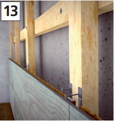
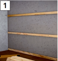
For this, the first row of wooden battens is mounted horizontally on the wall or ceiling, starting at the edge. To attach the substrate, use suitable wall plugs and screws. The load-bearing capacity must be designed for at least 10 kg per square meter of panels. Further supporting battens are mounted horizontally on the wall at a spacing of 40 cm over the surface [1].
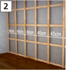
After this, the counter-battens are fitted onto the completed sub-construction. For this, starting at the end, the wooden battens are rotated by 90 degrees and screwed to the sub-construction, in a vertical alignment. In this case, once again, the spacing between the wooden battens is 40 cm [2].
Measure the area to be clad and calculate the number of panels required. Work with the opened packs without delay.
Wall-mounting of Kronowall 3D
[See images below]
3D Mounting System
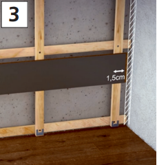
Ensure that the installation is tension-free. To ensure this, we recommend leaving an edging distance to the adjacent wall or ceiling and floor of at least 15 mm all around. A 15 mm edging distance must also be left to pillars, posts, supporting beams, door frames, radiator pipes, wall projections, etc [3].
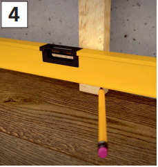
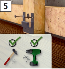
First start by attaching the 3D profile claw provided to the underside of the wall, directly on the counter battens. One profile claw is to be fitted to each counter batten. To ensure an even height, it is recommended that you mark out the position of the profile claws on the counter battens using a spirit level and a pencil [4].
The main body of the claw with the drilled holes is then positioned in such a way that the closed side faces downwards and the opened side upwards [5]. On the ceiling, the closed side is accordingly oriented towards the wall [6].
Nails can be used for mounting, using a pneumatic nail tacker or hammer. The 3D profile claws can also be screw-mounted to the substrate. This process applies to the entire wall-mounting. When assembling a ceiling, the profile claws are screw-fastened to the sub-construction.
After fitting the claws over the entire width of the all, the first row of wall panels are inserted longitudinally, with the groove inserted into the profile claws. In the first row, you are recommended to work only in one plane. This is Plane 1. Please maintain an edging distance of 15 mm.
Following the wall horizontally, further panels are similarly mounted onto the claws. To avoid openings at the joins, please guide each panel in a row with the short side directly abutting the short side of the previous panel. Rotate the last panel in the first row by 180° for trimming in or cutting to fit, placing it with the décor side facing upwards alongside the row and wall side that is already in place. Take into account the edging distance of 15 mm on the end face. Mark the panel length and saw to length. To avoid the edge splintering, the decor side should be face down when using electric compass saws or hand-held circular saws. Otherwise saw from the top side of the panel.
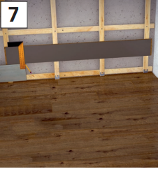
Ensure that the length of the last panel piece is not less than 50 cm so that at least two claws can hold it in place. If this is not the case, the length of the first panel in the first row must be adjusted accordingly [7].
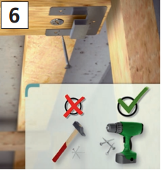
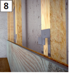
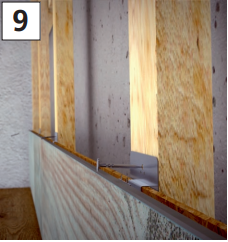
Before mounting the second row, the 3D profile claws are inserted onto the panels in the first row and attached to the counter battens. For this, a profile claw must be mounted into each counter batten. The profile claws are to be arranged in such a way that the opened side of the claw body faces downwards [8,9].
Start the second row either with a half-panel or the left-over piece from the first row. The second row is moved one plane in towards the room - as Plane 2.
In this case, the rear groove lip of the panel to be put into place serves as the tongue, which is introduced into the groove of the first row. In the same manner, the row is completed using further panels. Please ensure that the panel offset between the panels in adjoining rows is at least 20 cm.
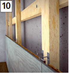
The last piece in the row must be cut to length. After this, the 3D profile claws are inserted onto the panels and attached to the counter battens. For this, a profile claw must be mounted into each counter batten. The main body of the claw with the drilled holes is then positioned in such a way that the closed side faces downwards and the opened side upwards [10].
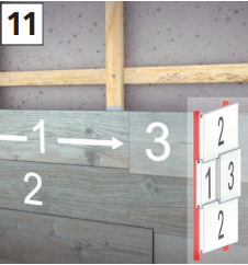
In the third row, essentially the work stages are carried out in the same way as for Row 1 (Plane 1). In this row, it is also possible to install and integrate Plane 3. The positioning and number of panels for Plane 3 are a matter of choice for you. To ensure panels are securely held in place, it is recommended that you start with a panel in Plane 1. In this case, the front groove lip of the panel to be put into place serves as the tongue which is introduced into the groove in the second row. After this, a panel can be inserted with its rear groove lip as the tongue into the groove in the second row, thereby creating Plane 3. This panel is to be run horizontally against the previous panel in this row (Plane 1).
A rebate on the short panel sides ensures a clean finish to the form [11].
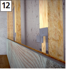
After this, further panels can be inserted in Plane 3 or Row 3 can be continued using a panel in Plane 1. All panels in Plane 1 in Row 3 are again to be secured using a 3D profile claw. For this, a profile claw must be mounted into each counter batten. The profile claws are to be arranged in such a way that the opened side of the claw body is facing downwards [12].
The panels in Plane 3 can be secured using 3D profile claws. For this, a profile claw must be mounted into each counter batten. The profile claws are to be arranged in such a way that the opened side of the claw body is facing upwards. The fastening of Plane 3 is achieved via the adjoining panel rows above and below [13].
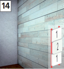
Generally, Row 1 must start with Plane 1 (panels lie directly on the counter battens). Then the complete Row 2 is mounted in Plane 2 (rear groove lip as a tongue in the groove on Row 1). The third row is fundamentally formed in the row for Plane 1. However, there is scope to integrate Plane 3. That means that the entire 3D wall is formed using a construction alternating between Plane 1 and Plane 2, and Plane 3 can only be integrated in Plane 1 rows.
However, it is possible to dispense with Plane 3 entirely and fit the wall using only Plane 1 and Plane 2 [14].
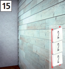
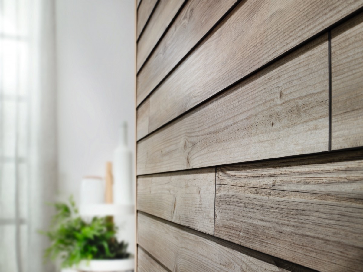
Clapboard Assembly System
This assembly system is characterized by the fact that the panels are attached horizontally to the wall and a shingle-like structure is achieved due to
the overlaps on the long sides [15].
Ensure that the installation is tension-free. To ensure this, we recommend leaving an edging distance to the adjacent wall or ceiling and floor of at
least 15 mm all round. A 15 mm edging distance must also be left to pillars, posts, supporting beams, door frames, radiator pipes, wall projections, etc. Start by attaching the 3D profile claws provided to the underside of the wall, directly onto the counter battens. A profile claw is to be fitted to each counter batten. The main body of the claw with the drilled holes is positioned in such a way that the closed side faces upwards and the opened side downwards. To ensure an even height, it is recommended that you mark out the position of the profile claws on the counter battens using a spirit level and pencil. Nails can be used for mounting, using a pneumatic nail tacker or hammer. The 3D profile claws can also be screw-mounted to the substrate. This process applies to the entire wall-mounting.
After fitting the claws over the entire width of the all, the first row of wall panels are inserted longitudinally, with the groove inserted into the profile
claws. Please leave an edging distance of 15 mm. Following the wall horizontally, further panels are similarly mounted onto the claws. To avoid openings at the joins, please guide each panel in a row with the short side directly abutting the short side of the previous panel. Rotate the last panel in the first row by 180° for trimming in or cutting to fit, placing it with the décor side facing upwards alongside the row and wall side that is already in place. Take into account the edging distance of 15 mm on the end face. Mark the panel length and saw to length. To avoid the edge splintering, the decor side should be face down when using electric compass saws or hand-held circular saws. Otherwise saw from the top side of the panel. Ensure that the length of the last panel piece is not less than 50 cm so that at least two claws can hold it in place. If this is not the case, the length of the first panel in the first row must be adjusted accordingly.
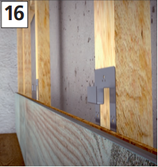
Before mounting the second row, the 3D profile claws are inserted onto the panels in the first row and attached to the counter battens. For this, a
profile claw must be mounted into each counter batten. The profile claws are to be arranged in such a way that the opened side of the profile body is facing downwards [16].
Start the second row either with a half-panel or the left-over piece from the first row. The second row is moved one plane in towards the room. In
this case, the rear groove lip of the panel to be put into place serves as the tongue, which is introduced into the groove of the first row. In the same
manner, the row is completed using further panels. Please ensure that the panel offset between the panels in adjoining rows is at least 20 cm. The
last piece in the row must be cut to length. After this, the 3D profile claws are inserted onto the panels and attached to the counter battens. For this, a profile claw must be mounted into each counter batten. The main body of the claw with the drilled holes is then positioned in such a way that the opened side faces downwards and the closed side upwards As a result, the panels are positioned at an angle to the wall. All further rows are attached in the same way.
Cleaning & Aftercare
• Use a hand-brush to remove any dirt which is loose.
• Stubborn dirt can be wiped off with a well-wrung out, drip-free cloth. Avoiding standing water at all times, particularly on the projecting panel edges.
• Cleaning must be carried out following the pattern, parallel to the longitudinal orientation of the panel.